
 Contact us now!
Guides · Marantec CS 320
Marantec CS 320 error codes and LED signals
Search by the displayed message or symptom. Display wording can vary with the controller language and software version.
Work on the control, operator and safety devices must be carried out by qualified personnel. Isolate the supply and secure against restarting before work. Follow the manufacturer’s instructions, including battery isolation and capacitor discharge times where applicable. Stop using a system with faulty safety devices or uncontrolled movement.
Use the manual for your exact control version. The following guidance helps to identify the affected area before a professional inspection. Manufacturer manual (PDF)
The table retains German display labels as search references and includes the corresponding English labels. Labels and menu numbering may differ by firmware. CS 320 FU uses its own manual.
Last updated: November 2026 · torautomation24 editorial team · Based on the official manufacturer manual
Controls and compatible spare parts

in stock
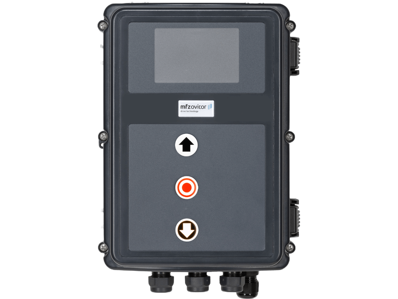
Control, operator and limit positions
| Code or observation | Meaning / possible cause | Checks and next steps | Buy spare parts |
|---|---|---|---|
| No response | Power supply may be missing | Have the incoming supply, fuses and voltage during starting checked by an electrician. | — |
| Opposite direction | Phase sequence may be incorrect | Stop the system. Have motor direction, mains phase sequence, encoder assignment and brake operation checked by qualified personnel. | — |
| FAULT – X | Internal hardware or software fault | Record the code and operating conditions and contact a qualified service technician. | — |
| ERROR RUNTIMEERROR LAUFZEIT | Programmed running time exceeded | Have the door path, blockages, limit switches and configured running time checked. | — |
| ERROR AWG | Absolute encoder position data disturbed | Have the encoder or limit-switch cable, connectors, signal and mechanical coupling checked before replacing components. | — |
| TERM SWITCH FAILERROR ENDLAGEN | Limit positions missing or outside the learned range | Have the limit-switch system, wiring, reference and stored end positions checked against the installation manual. | — |
| ERROR REVOLUTIONERROR KRAFT | Force monitoring activated | Have the door checked for stiffness, blockages, spring damage, imbalance and wind load before altering force settings. | — |
| ERROR DIRECTIONERROR DREHFELD | Three-phase supply sequence incorrect | Stop the system. Have motor direction, mains phase sequence, encoder assignment and brake operation checked by qualified personnel. | — |
Safety circuits and safety edges
| Code or observation | Meaning / possible cause | Checks and next steps | Buy spare parts |
|---|---|---|---|
| SAFETY CIRC.NOT-STOP | Safety circuit open | Have the affected safety circuit, contact, cable and termination checked. Keep the system out of service until the fault is resolved. | — |
| ERROR STOPERROR SICHERHEIT | Fault at safety input X4/11–12 configured as MOD8 | Have the affected safety circuit, contact, cable and termination checked. Keep the system out of service until the fault is resolved. | — |
| ERROR SKS CLOSEERROR SKS ZU | Closing safety edge 1 faulty | Have the safety edge, coiled cable, connectors, water ingress and configured sensor type checked. | View selection › |
| ERROR SKS OPEN 2ERROR SKS AUF 2 | Opening safety edge 2 faulty at input 2 | Have the safety edge, coiled cable, connectors, water ingress and configured sensor type checked. | View selection › |
| ERROR STOP. 2ERROR SICHERH. 2 | Safety circuit 2 open, including 8.2 kΩ wicket-door contact | Have the affected safety circuit, contact, cable and termination checked. Keep the system out of service until the fault is resolved. | — |
| ERROR SKS CLOSE 3ERROR SKS ZU 3 | Safety edge 3 faulty when closing, radio channel 1 at X20 | Have the safety edge, radio channel 1 and SKS 3 setting checked. | View selection › |
| ERROR SKS OPEN 3ERROR SKS AUF 3 | Safety edge 3 faulty when opening, radio channel 1 at X20 | Have the safety edge, radio channel 1 and SKS 3 setting checked. | View selection › |
| ERROR STOP. 3ERROR SICHERH. 3 | Safety circuit 3 open, radio channel 1 at X20 | Have the safety circuit and radio transmission checked. | — |
| ERROR SKS CLOSE 4ERROR SKS ZU 4 | Safety edge 4 faulty when closing, radio channel 2 at X20 | Have the safety edge, radio channel 2 and SKS 4 setting checked. | View selection › |
| ERROR SKS OPEN 4ERROR SKS AUF 4 | Safety edge 4 faulty when opening, radio channel 2 at X20 | Have the safety edge, radio channel 2 and SKS 4 setting checked. | View selection › |
| ERROR STOP. 4ERROR SICHERH. 4 | Safety circuit 4 open, radio channel 2 at X20 | Have the safety circuit and radio transmission checked. | — |
| ERROR SKS-TEST | Pneumatic edge or radio-system test failed | For pneumatic edges, check the profile, coiled cable and DW POINT. For radio systems, check the transmission and relay assignment. | View selection › |
| ERROR STOP-TEST | 8.2 kΩ wicket-door contact test failed | Have the affected safety circuit, contact, cable and termination checked. Keep the system out of service until the fault is resolved. | View selection › |
Sensors and additional modules
| Code or observation | Meaning / possible cause | Checks and next steps | Buy spare parts |
|---|---|---|---|
| ERROR LIGHT BAR.ERROR LICHTS. | Photocell fault at X4/1–4 | Check the travel area from a safe position. With the system stopped, check for dirty or obstructed optics. Have alignment, wiring and function checked if the fault persists. | — |
| ERROR LIGHT BAR. 2ERROR LICHTS. 2 | Photocell fault at X4/9–10 | Check the travel area from a safe position. With the system stopped, check for dirty or obstructed optics. Have alignment, wiring and function checked if the fault persists. | View selection › |
| ERROR LB TESTERROR LS-TEST | Two-wire photocell test failed | Have the connected safety device, supply, wiring and test signal checked. Keep the system out of service if protection is faulty. | View selection › |
| ERROR TRAPINERROR EINZUG | Draw-in protection test failed at additional module | Have the connected safety device, supply, wiring and test signal checked. Keep the system out of service if protection is faulty. | — |
| ERROR CYLINDERERROR ZYLINDER | Wicket-door lock feedback missing after ten seconds | Have the lock, cylinder limit switch and feedback wiring checked. | — |
| ERROR MSBUS | Communication with MS-BUS module interrupted | Have the module, bus wiring, plugs and power supply checked. Record recurring interruptions. | — |
Supply and circuit board
| Code or observation | Meaning / possible cause | Checks and next steps | Buy spare parts |
|---|---|---|---|
| ERROR 24 V | External 24 V supply disabled due to overload | Have the connected loads checked. The manual specifies a total maximum of 500 mA for external sensors. | — |
| ERROR POWERSEGM.ERROR LASTTEIL | Power contactor or relay faulty | Have the exact control version identified and the circuit board tested before selecting a replacement. | Buy › |
| ERROR BRAKEERROR BREMSE / ERORR BREMSE | BWM1 reports a fault at relay 4 | Have the exact control version identified and the circuit board tested before selecting a replacement. | Buy › |
LED and status displays
| Signal | Meaning / possible cause |
|---|---|
| H1 green off | Power supply may be missing |
| H2 red flashes 1× | SAFETY CIRC. |
| H2 red flashes 2× | ERROR AWG |
| H2 red flashes 3× | TERM SWITCH FAIL |
| H2 red flashes 4× | ERROR DIRECTION |
| H2 red flashes 5× | ERROR REVOLUTION |
| H2 red flashes 6× | ERROR RUNTIME |
| H2 red flashes 9× | ERROR MSBUS |
| H2 red flashes 11× | ERROR POWERSEGM. |
| H2 red flashes 10× | service interval reached |
| H2 red steady light · no movement | ERROR STOP |
| H2 red steady light · hold-to-run movement only | SKS |
| H2 red steady light · closing only in hold-to-run mode | ERROR LIGHT BAR. |
Fault memory and restart
The LCD DIAGNOSIS mode shows stored messages, occurrence count and the cycle of the latest event. Use + and − to browse. Record these values before deleting or restarting. After correcting direction, force, runtime or limit-position faults, follow the restart procedure for the installed software.
Frequently asked questions
Does a fault code identify a defective part?
It identifies the affected function or circuit. Wiring, adjustment, supply and mechanics can cause similar messages. Have the cause checked before replacing a component.
Which information should I send with a compatibility enquiry?
Send the rating plate, control part number, supply voltage, software version where available and the full fault message. For radio issues, include transmitter and receiver details.
Can I acknowledge or reset a fault immediately?
Resolve the cause first. Reset procedures and learning runs vary by model, and a factory reset may erase settings. Follow the manual for the installed version.